Building Information Modeling
This involves the study of the current applications of Building Information Modeling (BIM) in Architecture, Engineering & Construction (AEC). This project intends to expose students to the various current applications in the AEC industries, through an in-depth review of the literature. The findings are presented in the form of an infographic.
Project 1: Infographic Board
Students are to identify ONE specific area from the following and conduct a literature review based on case studies of application / research in BIM:
• Project Management • Digital Heritage & Conservation • Energy Analysis • Risk Assessment • Geographical Information System (GIS) • Virtual Prototyping

PROJECT 2A
BUILDING MODELLING
Task
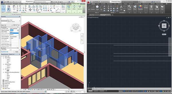
1. Based on the selected architectural design, you are to generate a Revit model. The model must be compliant with LOD200 requirements (refer Appendix 1).
2. Your Revit model must include at least TWO Revit Family components.
3. You are required to create a blog or Facebook album for public access. The Work in Progress (WIP) print screens and test renderings must be uploaded to the above online platform REGULARLY to show progressive evidence of the working process. It will serve as a communication and mutual learning platform. You are encouraged to visit your peers’ WIP and give constructive comments and suggestions.
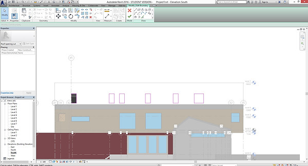
In this project, The Dell by Elliott Architects chosen as a building reference.

1. Grid line is drawn as horizontal and vertical, key in the distance between grids by selecting the grid line and click into the dimension. The label of grids are changed accordingly to alphabetical and numeric order.
Add Dimension with a shortcut key 'di' follow by selecting two grid line.

2. Select wall under Architecture, click edit type to change the material. Duplicate the wall type and create a new wall type and change the material.


adding plan views/ extra views under : view > plan view > floor plan (or others designated view)

The wall was accordingly by following the grid line in Level 1. Repeat the same method in Level 2.
Flooring was created under architecture tab > floor.
In Modify Tab, Line Tool was used to drawing a close loop boundaries of the floor and click the green tick. Repeat the same method for Level 2 floor.
The material of the flooring was changed under "edit type>material "to suit the desirable outcome.

Create staircase
Architecture > Stair > Stair by sketch


building windows that sit on top of the roof.
steps:
cut our openings on the roof using "opening by face", choose the face you want to cut with, draw the shape that you want to clear out.


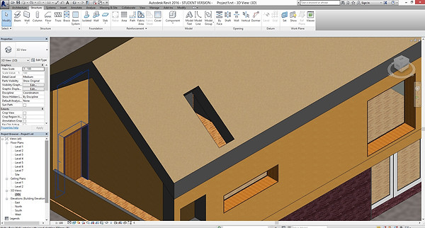

building windows that sit on top of the roof.
steps:
now, to make the window.
choose component > model in-place> choose window.


first, draw out the frame f the window, follow up with the glass.
you can change the material of the model under properties tab, materials.


Family 1 Door Family
A new family template is created and preferably choose Metric Door. With shortcut key of reference plan, 'rp', draw reference line of door frame thickness.
Add dimension 'di' to the reference plan drawn. Add parameters to the door frame thickness in Parameter Properties. Make sure Family Parameter and Type are chosen. Name the parameter under parameter data. Check or change the dimension in Family type.
Assign the parameter and dimension to the reference plan.
Under Create Tab, select Extrusion. Draw a boundary line for the door frame and key in the preferred depth before clicking the green tick
In both ref. level and elevation view, make sure the parameter are lock and constraint.
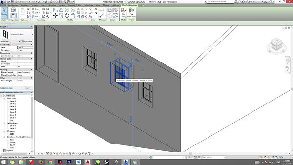
Load the new door family and put the door at the proper position at floor plans.


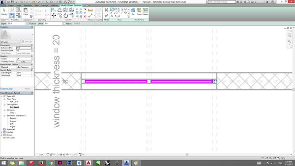
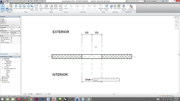
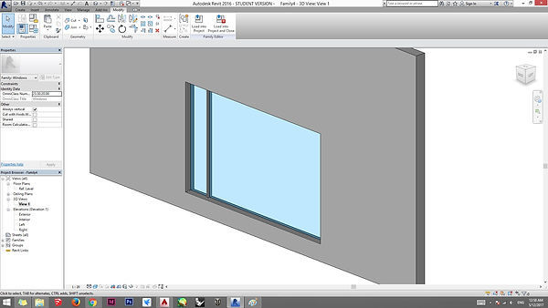
Family 2 Windows
Create a new window family template.
Same method as the Door Family, draw reference plan of the window frame at exterior elevation view.
Add Dimension and Parameters to the window frame thickness.
Check and change the dimension of the window frame in Family Type.
Determine the Panel Distance in Family Type.
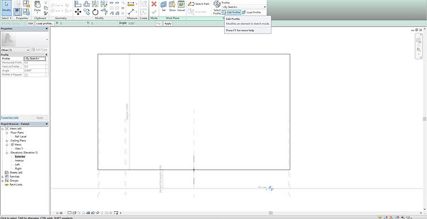
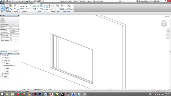
Under Create Tab, select Extrusion and draw the window frame and change the depth of it. Lock the Constraint of each edge of the frame.
After changing the material of the window, the window family is done.
Load the window family into the project.


Family 2 Windows
Create a new window family template.
Same method as the Door Family, draw reference plan of the window frame at exterior elevation view.
Add Dimension and Parameters to the window frame thickness.
Check and change the dimension of the window frame in Family Type.
Determine the Panel Distance in Family Type.
Under Create Tab, select Extrusion and draw the window frame and change the depth of it. Lock the Constraint of each edge of the frame.
After changing the material of the window, the window family is done.
Load the window family into the project.


some resources found online and step how to import family into a project.
by the modify tab "import family". it dimension was changed by the properties tab.


outcome


